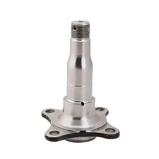
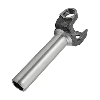
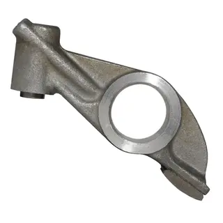
In modern industrial production, shaft forgings play an indispensable role. From large-scale machinery to precision instruments, shaft forgings are core components. They not only bear the critical tasks of transmitting power and motion but also directly impact the performance, efficiency, and service life of mechanical equipment. Applications of shaft forgings are widespread, from automotive engine crankshafts to industrial machine tool spindles, from precision aerospace components to various common mechanical devices in daily life. The complexity of their manufacturing process, diversity of material selection, precision in structural design, and strict quality control collectively determine the final performance of shaft forgings.
Shaft forgings are produced through a forging process to create blanks or workpieces. This technique, known as "open-die forging," is commonly referred to as the smith forging process. The forging process involves several key steps.
The heated metal is first secured on an anvil, then shaped into a cylindrical form using horizontal or vertical dies. This step is crucial as it provides the basic structural stability and significantly enhances the physical strength of the shaft forging. By precisely controlling the die pressure and direction, the metal undergoes plastic deformation at high temperature, achieving the desired shape.
After preliminary shaping, the cylindrical metal rod undergoes further processing to achieve the required length, thickness, and form. Multiple dies are applied simultaneously to deform the rod along its length and ensure the target thickness. Accurate die design and operation ensure dimensional precision in line with design requirements.
To further optimize the shape and performance, trimming and upsetting are performed. Concave dies concentrate material at the ends, while convex dies press thin layers onto the workpiece. This process removes excess material, improves surface quality, and reduces subsequent machining difficulty and costs.
Flattening is the final step in shaft forging, smoothing the surface to achieve a clean finish. While it may not eliminate all surface defects, it significantly reduces subsequent machining costs and enhances production efficiency.
Before forging, the workpiece is preheated. Heating temperatures and durations vary by material, requiring careful control. Material grade, furnace number, dimensions, and quantity must be verified. The furnace must be clean, and the workpiece free of oil contamination. Workpieces should be arranged for uniform heating, with measures to prevent overheating, control scale thickness, and minimize decarburization according to forging requirements.
The choice of material for shaft forgings is critical to their performance and service life. Commonly used materials include carbon steel and alloy steel, each offering distinct properties and suitable applications.
Carbon steel is widely used due to its well-rounded mechanical properties. High-quality carbon structural steels such as 35, 45, and 50 are the preferred materials for shaft forgings, with 45 steel being especially popular for its excellent overall performance. To further enhance its mechanical properties, normalizing or quenching and tempering treatments are often applied. For less critical shafts or those subjected to lower loads, carbon structural steels like Q235 and Q275 can also be used.
Alloy steel offers superior mechanical properties but is relatively more expensive, so it is typically reserved for shafts with special requirements. For example, high-speed shafts with sliding bearings commonly use low-carbon alloy steels such as 20Cr and 20CrMnTi. After carburizing and quenching, these materials significantly improve the wear resistance of the shaft journals. Rotor shafts of steam turbines and generators, which operate under high temperature, high speed, and heavy loads, often use alloy structural steels like 40CrNi and 38CrMoAlA, which provide excellent high-temperature mechanical performance.
The structural design of shaft forgings is a crucial step in determining their optimal shape and overall dimensions. Designers must consider multiple factors, including the types, sizes, and positions of components mounted on the shaft, methods of component fixation, the nature, direction, magnitude, and distribution of loads, types and dimensions of bearings, the shaft blank, manufacturing and assembly processes, installation and transportation, and potential shaft deformations. The following are some common principles for structural design:
When designing a shaft, it is advisable to use shapes with uniform strength to minimize material usage and reduce the shaft’s weight. Additionally, cross-sectional shapes with larger sectional modulus should be selected to enhance the shaft’s strength and rigidity.
Shafts often carry components with hubs, so most shafts are designed as stepped shafts with larger machining allowances. The design should ensure accurate positioning, stability, ease of assembly and disassembly, and convenient adjustment of components. A well-designed shaft structure improves installation efficiency and component reliability.
Stress concentration is a major cause of shaft failure. Structural measures such as fillets and grooves should be incorporated in the design to reduce stress concentrations, thereby enhancing the shaft’s strength and service life.
The manufacturability and precision of a shaft significantly affect its performance. The design should consider ease of manufacturing and adopt structures that are simple to produce. At the same time, it is essential to ensure that dimensional accuracy, geometric precision, and relative positioning of features meet design requirements.
Shaft forgings can be categorized into various types based on their structural shape and intended application, including crankshafts, straight shafts, flexible shafts, solid shafts, hollow shafts, rigid shafts, and elastic (flexible) shafts. Each type has distinct characteristics and suitable applications.
Crankshafts: Crankshafts are critical components in engines, converting the reciprocating motion of pistons into rotational motion. Due to their complex structure, crankshafts are usually manufactured as forgings to ensure sufficient strength and rigidity.
Straight Shafts: Straight shafts are simple shafts primarily used for transmitting motion and torque. Their simple structure results in lower manufacturing costs, making them suitable for a wide range of machinery.
Flexible Shafts: Flexible shafts possess elasticity, allowing them to accommodate complex motion requirements. They are commonly used in applications requiring flexible transmission, such as automotive steering systems.
Solid and Hollow Shafts: Shafts are also classified according to their internal structure. Solid shafts offer higher strength but are heavier, whereas hollow shafts provide a higher strength-to-weight ratio, making them ideal for applications where weight is a critical concern.
Rigid and Flexible Shafts: Rigid shafts have high stiffness and are suitable for applications that require support for heavy loads. Flexible shafts, on the other hand, offer higher elasticity and can adapt to complex motions and deformations.
Shaft forgings are widely used in various mechanical systems, and their performance and precision directly affect the efficiency and reliability of equipment. Common application areas include:
In vehicles such as cars and motorcycles, shaft forgings are commonly used in transmission components, such as drive shafts and crankshafts. These shafts transmit engine power and drive the vehicle. Their performance directly impacts power transfer efficiency and operational stability.
In machine tools such as lathes and milling machines, shaft forgings support and drive various cutting tools. The precision and strength of these shafts are crucial for the quality and accuracy of machined components.
In industrial automation, shaft forgings are used to drive mechanical components such as robot joints and conveyor systems. Their reliability and precision are essential for operational efficiency and production quality.
In the aerospace sector, shaft forgings are used in critical components such as engines and flight control systems. These components must perform under extreme conditions, placing very high demands on the material, structure, and performance of the shafts.
Ensuring performance and reliability requires strict quality control:
Includes shaft diameter and length tolerances. Main journal diameters typically meet IT6–IT9, precision journals up to IT5. Step shaft lengths follow nominal dimensions with specific tolerances per step.
Roundness and cylindricity are important. For general precision, geometric error should remain within diameter tolerance; higher precision requires explicit drawing tolerances.
Concentricity of journals relative to supporting journals is critical. Radial runout tolerance is 0.01–0.03mm for general shafts, 0.001–0.005mm for high-precision shafts. Other positional accuracy includes coaxiality of internal/external cylinders and perpendicularity of axial end faces to the shaft axis.
Surface roughness depends on machine precision and operating speed. Support journals: Ra 0.63–0.16μm; mating journals: Ra 2.5–0.63μm. Roughness affects wear resistance, fatigue strength, and mating quality with bearings.
As a critical component in mechanical manufacturing, shaft forgings’ performance and reliability depend on forging process, material selection, structural design, and quality control. From precise forging operations and scientific material selection to optimized structural design and strict quality inspection, every step is essential. Mastery of these factors ensures stable performance under complex working conditions and provides a solid foundation for efficient industrial production.


